9/13/17 - Gimme a beat
My shipment from Mouser came in, and my desk is now covered in ICs, resistors, LEDs, and jumpers.
Ciarcia’s book and other sources online start the building process off with the clock, so I did the same. This was my first time working with ICs, and the clock seemed like a simple and rewarding place to start. Flashing LEDs will can make anyone feel like they’ve made something cool.
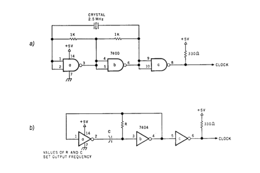
My first attempt at a functioning clock was Ciarcia’s single step design using a 7000, 7404, and an SPDT switch. This seemed simple enough, just like any circuit where a component is turned on with a switch. I also set up the slow clock, made with a 7404, capacitor, and resistor, as pictured in the book. A 4-pin DIP switch block selected between the two clock circuits.
I had trouble testing and getting any validation from these circuits though. I tried hooking an LED up to the circuit’s output and connecting the cathode to ground, but I think this resulted in the LED emitting all the time due to the clocks 330 Ohm pullup to 5V. At the time, I hadn’t realized how IC logic worked outside of putting a high or low voltage signal in on one side and recieving a high or low voltage signal out of the other side. It took a day or two to discover that an LED could reach ground through an ICs output when the output pin was in a low state. For now, I took the circuits apart, cleaned up, and called it a night.
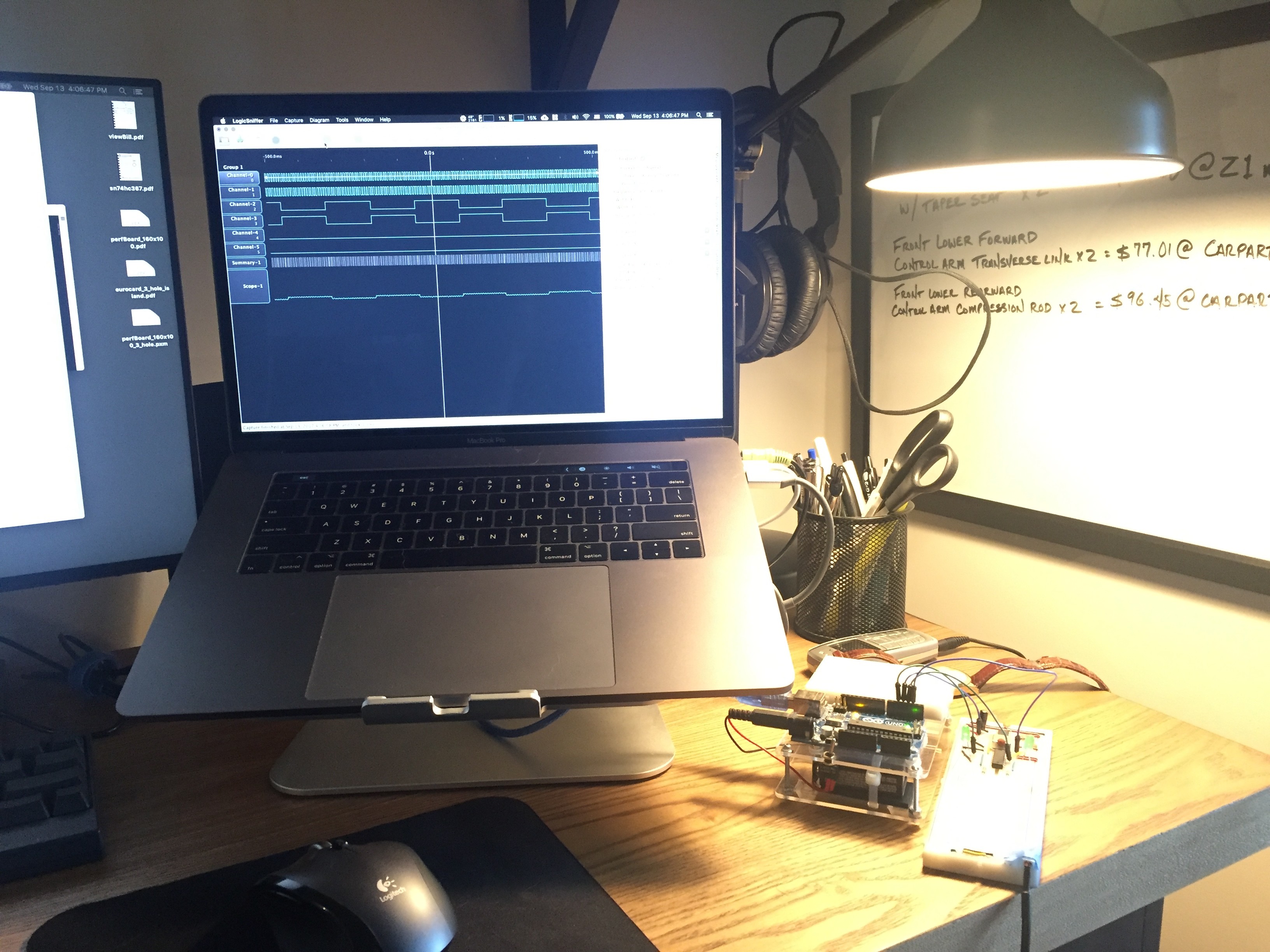
The next day, I tried to make sense of the previous night’s errors. I tried to put together a logic probe circuit, but lacked some of the materials. I figured that my Arduino might be able to read logic high or low through the input pins, so I searched online to see if anyone had set up an Arduino as a probe. I found a few solutions that not only worked as a probe, but even as a full-blown multi-channel logic analyzer. Hell yeah! Setup was simple enough: upload the sketch to the Arduino, choose a port and baud rate, and launch the LogicSniffer software. The sketch implements a protocol fot interfacing with the open-source logic analyzer software. I set up a manual clock circuit as a I had the previous day, then started up the analyzer. I flipped the switch and captured data from the device a few times and was able to see the input switching between high and low. Seems like everything had actually been working, but I just couldn’t see it before due to wiring errors.
If you want to try the logic analyzer, you can find the Arduino sketch on Github here and the LogicSniffer software at the creator’s website here.
Feeling a little more confident and prepared, I watched Julian Ilett’s Z80 video again. He seemed to set everything up so quickly and easily, so I attempted to copy that. Julian used a simple 555 astable circuit to clock his Z80, and the 555’s output was even able to power an LED to show the clock’s pulse. I found a website for calculating 555 timer setups and figured out what I’d need to get a circuit that would flash around 4 times per second with almost a 50% duty cycle. I dug the components out of my drawers and got a similar set up and working. The first flashing LED; cool!
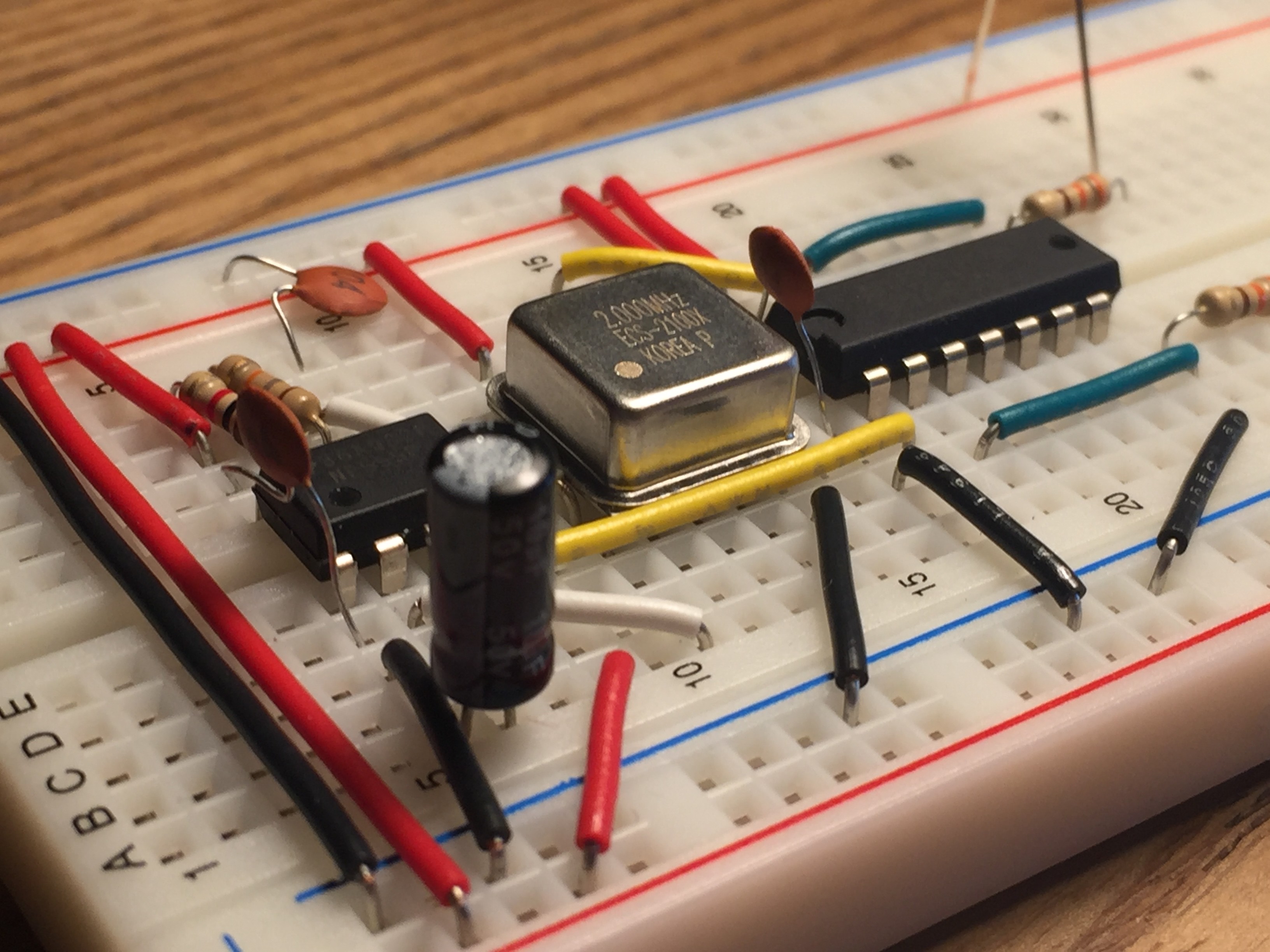
After getting the slow clock set up, I was anxious to get the blazing 2 MHz oscillator from Mouser up and running. The clock I bought was an all-in-one crystal oscillator circuit. All I had to do was hook up 5V and ground to have a perfect clock.
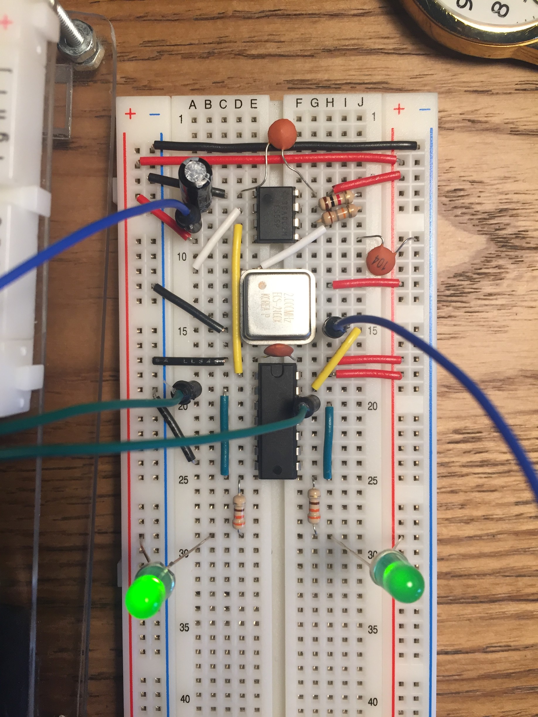
I ran both outputs through a 7404 before hooking up the LEDs so I could measure the real outputs, take some current off the ICs, and still have flashing light to match the clock pulses. The 555’s LED was looking great, but the oscillator’s LED stayed a dull green. That seemed like it might be correct though, due to the circuit toggling 2 million times per second.

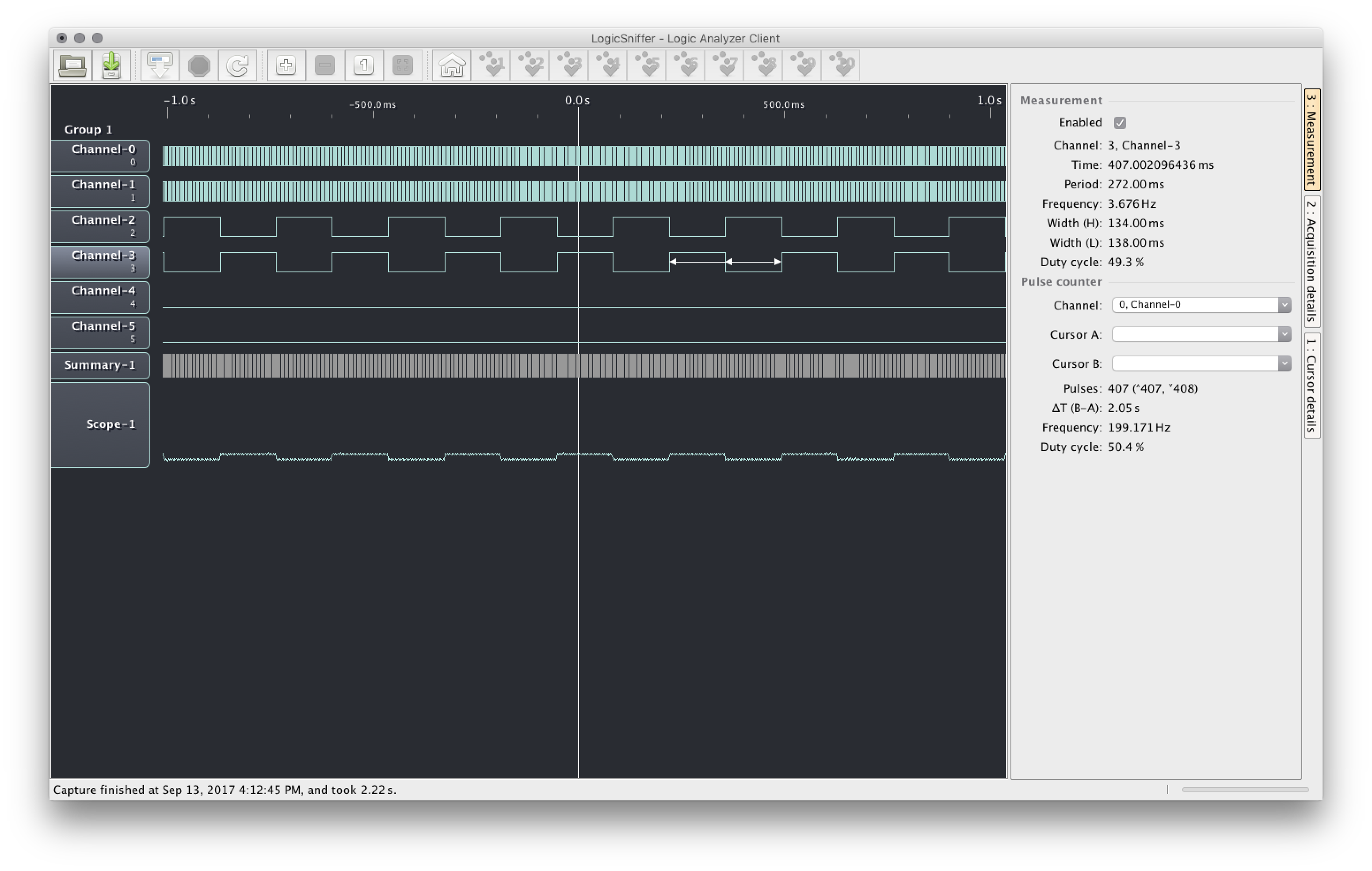
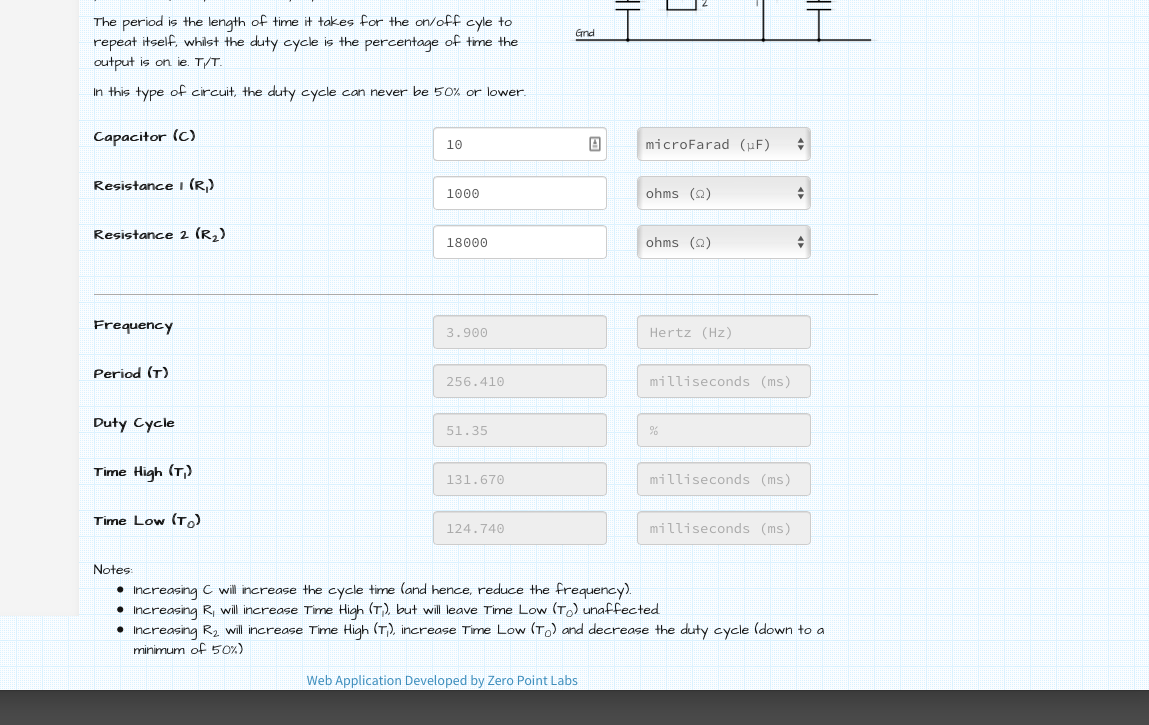
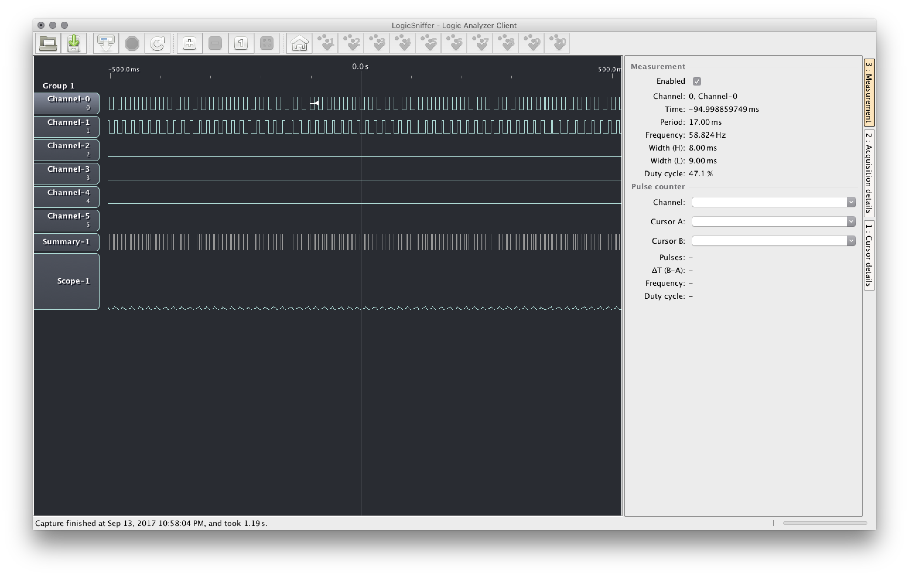
To be sure, I hooked both up to the Arduino’s digital pins and started up LogicSniffer. The captured data looked great! My 555’s wavelengths were uniform, and the oscillator was putting out a perfect 2 MHz square wave. I did notice that the 555’s frequency was a bit slower than the value from the calculator. Off by like 0.3 Hz even, which seems like a lot when the calculated frequency was only about 3.9 Hz to start with. Perhaps this is what the resistor tolerance is about. I’m using an 18k resistor in the 555, so if it’s 5-10% off, the actual frequency may be correct after all.
The analyzer started acting up after a few more captures, especially when I got the clock selector switch up in the mix. A consistant pattern started to emerge on any channels with a wire inserted, and I eventually noticed that the strange wave was at 60 Hz, which must be interference. No amount of unplugging and restarting could make the interference go away. I tried using decoupling capacitors and pullup resistors, but those didn’t make a difference either. When I disconnected my clocks from the Arduino, I saw that the interference was still there, so my clocks probably aren’t the issue. Even with the interference problem, I highly recommend LogicSniffer if you’re broke and clueless like me.